|
 |
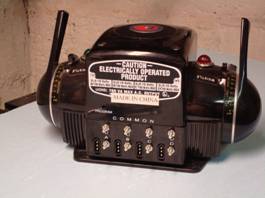
Starting
with the ZW controller, make sure it is disconnected from all power
before beginning. The knurled nuts have already been removed and put in
a safe place. The tools I used for this repair
included an 11/32 nut driver, a medium sized Phillips screwdriver, a
small Flathead screwdriver and a small pair of needle nose pliers.
An ESD wrist strap is also recommended any time you work on
electronics. It is very important to have a clean, well-lit area to work
in. I would also recommend a small container to hold
the hardware that is removed for safekeeping. |
|
 |
Using
the Phillips screwdriver, remove the 4 screws on the top cover and set
them aside. Carefully remove
the cover and place it out of harms way.
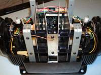
The circuit board is held in place by the terminals and supported
by plastic retainers that hold the heat sink panels in place.
This view is from the front of the controller and shows the heat
sink supports and antenna. The
circuit board is in the background and the chip is visible just below
the connectors. |
|
 |
Take
all the screws out of the top heat sink support including the screw on
the antenna. Remove the top
support by gently twisting it up or down and sliding it out the side.
Remove the antenna’s bottom screw and carefully tuck it inside
the case to the side. Remove
the remaining 2 screws on the lower support and removed it the same way
as the upper supports.
All
these screws are the same size so there is no need to worry about which
go where. |
|

|
Next
remove the 2 uprights closest to the circuit board.
The screws are on the bottom of the controller.
There is a nut, washer, and lock washer that will fall free
inside the ZW for each upright. Make
sure you get them all out and account for them.
You may need to use your finger to keep the nut from spinning.
The nuts are not that tight and should break free with just the
screwdriver. Set the
uprights to the side.
|
|

|
Now
remove the nuts on the terminals. The
11/32 nut driver fits them. Keep
in mind that the supports for the heat sinks are no longer supporting
them so take care in not moving or bumping them.
The circuit board assembly now has minimal support so continue
carefully.
|
|
 |
Next
take care in removing the 2 control connectors and the antenna connector
from the circuit board. They’ll
hang in place and you’ll have to be careful when the board is removed.
They’ll pretty much stay in place as to where they go when the
time comes to reconnect them.
|
|

|
Carefully
tip the heat sinks up and slide the terminals out of the holes.
Watch that the board doesn’t get caught on the wiring harness.
Also be very careful not to put too much pressure on the heat
sinks. You do not want to
move them around or bump them. They
are attached to the board by components and do not have much support.
|
Click
on image for larger version.
|
With
everything out this is what you should have.
This is all the screws and parts that I removed to get the board
out. At this point you
should have…
- 4
screws for the cover.
- 6
screws for the heat sink supports and antenna.
- 2
heat sink supports.
- 8
nuts for the terminals.
- 2
uprights each with a screw, a washer, a lock washer, and nut.
- The
circuit board assembly with heat sinks.
|
Click
on image for larger version.
|
Now
look at the circuit board. Note the orientation of the chip and note the
indent on the end of the chip (Red Arrow).
The new chip has to go in the same way.
You can damage the new chip if not inserted the same way.
Carefully take the chip out of the socket. Gently use a very small flat
screwdriver to pry it up from both ends a little at a time until it is
completely loose.
Install
the new chip remembering the correct orientation (Indent matching with
line on the circuit board). Be
careful to get all the pins in the socket.
You may need to bend them in a little.
I do this by putting one side on a hard service and apply slight
pressure on the entire row of pins.
Take your time and do this a little bit at a time until the pins
line up correctly with the socket. If
they are far off I usually bend each row a little rather than one row of
pins a lot.
|
|
Once
the new chip in installed and you have confirmed that all the pins are
properly seated in the connector, re-install the board and heat sink
assembly the same way it came out. Tilt
it back into place. Put the
nuts back on the terminals and tighten them being careful not to over do
it. Re-install the black
supports for the heat sinks and the antenna.
Reconnect the 2 control connectors and antenna to the circuit
board.
|
 |
Next
is probably the hardest part, trying to get the uprights back in.
It’s a balancing act of getting the screw through the bottom,
the upright on, and all the hardware back together.
Once the screw is through the bottom the upright goes first
facing the same way as the others that were not removed. The washer is
next, the lock washer and then the nut.
It takes a little patience but it’s not too bad.
A piece of tape over the screw might help keep it in place while
putting the other hardware on. Tighten it all up.
Check all your connections; look for any possibly pinched wires.
|
|
Click
on image for larger version.
|
Once
all back together, before the top is back on this is what you should
have. Re-check your work.
Make sure the antenna wire will be clear when you put the top on. Carefully
put the cover back on making sure the direction/whistle and bell buttons
line up with their respective holes. It
should seat completely onto the bottom case.
You may have to align the uprights a little to get the screws in.
The holes in the uprights should be visible and not needing major
aligning. If they do they
are not installed correctly.
|
|
This
pretty much covers the chip replacement.
Be sure to take your time and check your work.
Make sure your new chip is oriented correctly and all the
connections are restored. Reconnect
the ZW to your layout and you should be good to go.
It’s
not a hard project and should take at most 1 hour if you really take
your time. No soldering is
needed and just some basic mechanical skills are required.
In reality you could take this to your local service center or
Lionel but I think it’s something that most folks can handle
especially with some direction.
That
being said, I cannot stress this enough…
If
you are NOT comfortable with this procedure let a service center or
Lionel do the work.
Lionel
is not responsible for anything contained in this hand out.
Lionel or I assume no responsibility for any damage that results.
All work is done at your own risk. |